

FPiGA Audio Hat Meets RadHDL
The FPiGA Audio Hat project is a practical demonstration of what RadHDL is meant to make possible: portable, reusable FPGA design that still maps cleanly onto real silicon resources. The project takes a Gowin-based audio design and turns it into a board-level RadHDL integration target with I2C control, Raspberry Pi-facing I2S, codec ADC/DAC I2S, wavetable synthesis, polyphonic voice generation, modulation, stereo processing, and integrated debug capture.
This matters because audio DSP is one of the clearest domains where FPGA acceleration is not just interesting, but natural. Audio arrives on a strict schedule. Every sample has a deadline. The math is predictable, repetitive, and often multiply-heavy. A CPU can certainly synthesize, mix, and filter audio, but it does so through a software runtime that has to share caches, interrupts, threads, drivers, and memory bandwidth with everything else in the system. An FPGA lets the audio engine become a deterministic hardware pipeline.
In this project, RadHDL is doing two jobs at once. First, it provides the reusable blocks: register interfaces, I2S bridges, DSP engines, primitive wrappers, and debug capture. Second, it gives the design a structure that can keep growing. Instead of building a one-off board demo that only exists as a local HDL pile, the FPiGA Audio Hat becomes an example of how a portable HDL library can support serious mixed hardware/software products.
Why FPGA Audio Is Compelling
Audio systems are dominated by regular time-domain work. At 48 ksample/s, each stereo sample frame arrives every 20.83 microseconds. Within that window a design may need to receive I2S samples, apply gain, mix multiple sources, update oscillators, interpolate wavetable values, process envelopes, apply panning, run EQ, and produce a clean DAC stream.
On a general-purpose CPU, the implementation has to be careful about callback timing, context switches, memory locality, priority inversion, and driver behavior. Modern CPUs are extremely fast, but they are not inherently sample-synchronous. An FPGA is different: the datapath can be built around the sample clock and the audio frame itself.
That gives several advantages:
The I2S clocks and LRCK boundaries can directly define when work happens.
Oscillators, mixers, interpolation stages, envelopes, and filters can be pipelined.
Multiple channels and voices can execute in parallel or on a deterministic TDM schedule.
DSP slices and block RAMs can be allocated deliberately instead of left to a compiler/runtime.
Latency is controlled by the hardware schedule, not by a host audio callback.
Debug visibility can be integrated into the fabric through RadILA and RadDebugHub.
The result is not just "a faster synth." It is a design style where timing, routing, debug, and audio behavior are all explicit parts of the hardware architecture.
Project Architecture
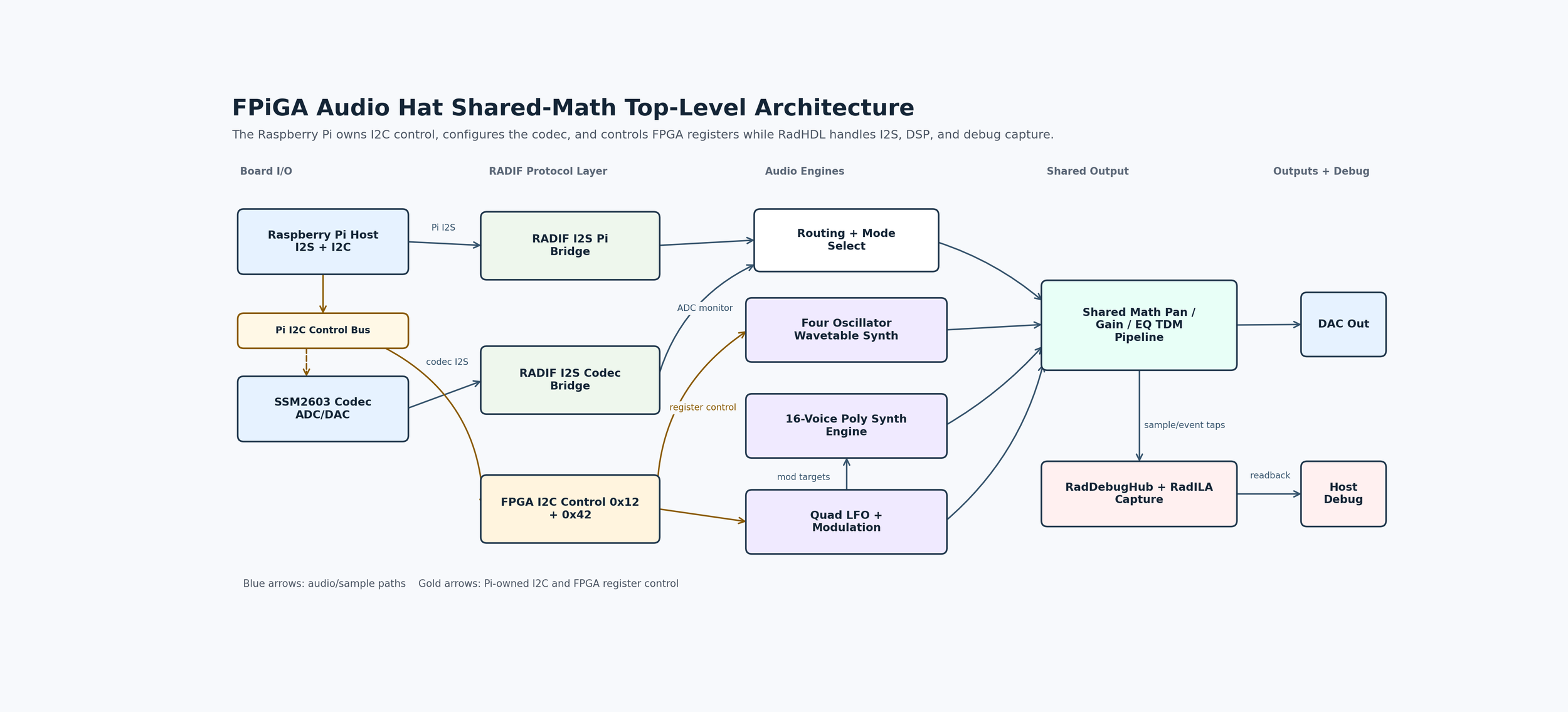
The current top-level design is `radhdl_fpiga_audio_top`. It exposes a 50 MHz input clock, an I2C control bus, an audio master clock output for the SSM2603-style codec path, codec-facing I2S, Raspberry Pi-facing I2S, mute control, and debug pins.
At a high level, the design is split into five regions:
1Board I/O: Raspberry Pi I2S, codec I2S, I2C control, MCLK generation, and mute/debug pins.
RADIF interfaces: reusable I2C and I2S adapters that convert board-level protocol traffic into clean internal transactions and sample lanes.
Audio engines: ADC monitor routing, four-oscillator wavetable synthesis, polyphonic synthesis, and LFO modulation.
.Shared output processing: pan, gain, and EQ-style processing using a deterministic shared-math datapath.
Debug capture: RadDebugHub and RadILA infrastructure exposed through the same register model.
The Raspberry Pi acts as the I2C controller in this system. It configures the SSM2603 codec and also drives the FPGA's I2C-visible control/register path. The main FPGA audio/control block is exposed at `0x12`, while the debug hub is exposed separately at `0x42`. This gives software a simple bring-up model: one bus can configure the codec, audio routing, synthesis, gains, panning, oscillator state, and debug capture without needing vendor debug tooling.
RadHDL Building Blocks
The port replaces board-local glue with reusable RadHDL subsystems:
| Board Function | RadHDL Implementation |
|---|---|
| I2C register control | radif_i2c_slave_to_reg |
| Register storage | radif_reg_bank, radif_reg_interconnect |
| Pi I2S Bridge | radif_i2s_axis |
| Codec I2S bridge | radif_i2s_axis |
| Debug access | RadDebugHub, RadILA |
| Four-oscillator dds | raddsp_audio_quad_wavetable_oscillator |
| Oscillator pan/mix | raddsp_audio_quad_osc_pan_mixer |
| LFO modulation | raddsp_audio_quad_lfo_wavetable |
| Polyphonic synthesis | raddsp_audio_poly_synth |
| Shared output path | raddsp_audio_stereo_shared_pg_eq_tdm |
| Gowin primitives | Explicit Gowin primitive wrappers |
This is the major architectural improvement. The design is no longer a closed Gowin-only example. The board target still uses Gowin resources, but the higher-level audio architecture is expressed through reusable RadHDL interfaces and DSP blocks. As RadPrimitive expands, the same structure can be retargeted toward other FPGA families with less rewrite pressure.
Synthesizer Capability
The current design already supports several meaningful modes:
Raspberry Pi playback through the FPGA path.
Codec ADC monitor mode into the DAC.
ADC plus generated audio mixing.
Four-oscillator wavetable synthesis.
A sixteen-voice polyphonic wavetable synth path.
Quad LFO modulation for oscillator and pan targets.
Shared stereo gain, pan, and EQ-oriented processing.
I2C-visible register configuration and debug capture.
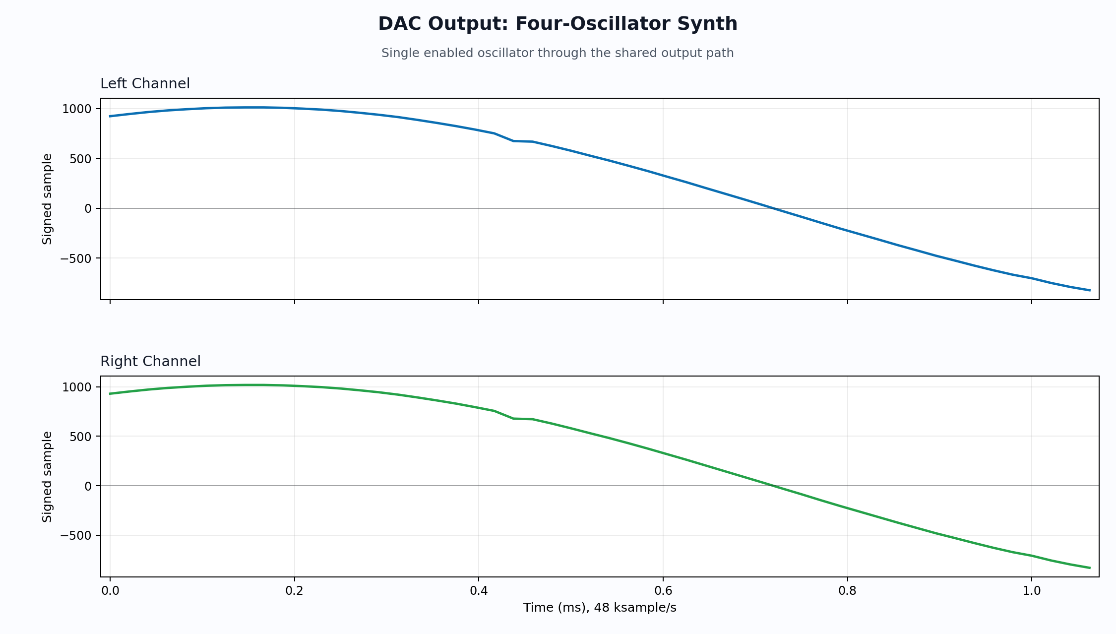
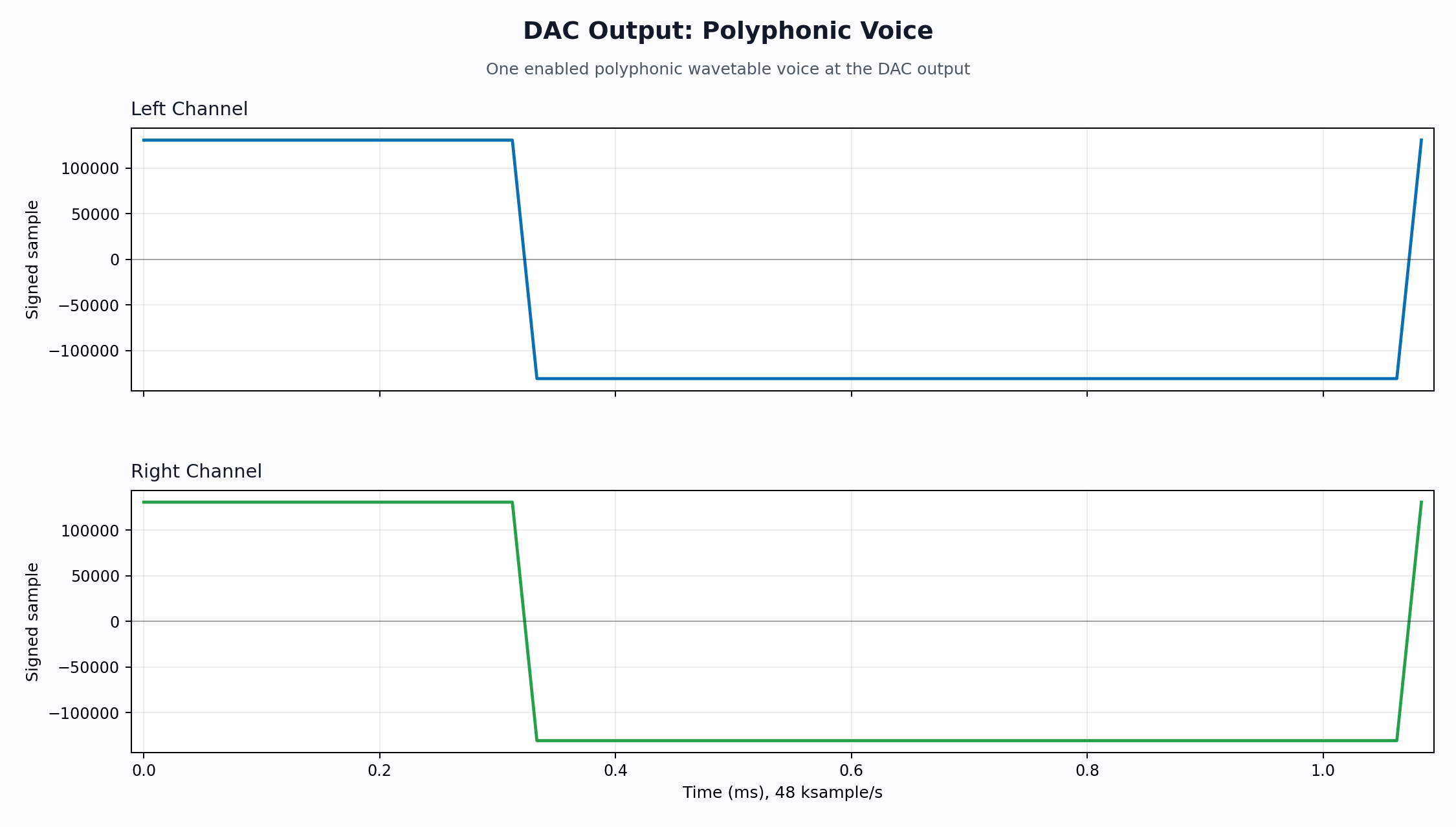
The four-oscillator path uses phase accumulators, wavetable lookup, interpolation, per-oscillator gain, and pan control. The polyphonic path gives each voice frequency, gate/enable, packed waveform volume settings, and ADSR control. This is already enough to act as the core of a compact FPGA synthesizer, and it is structured so more control software can be layered on top.
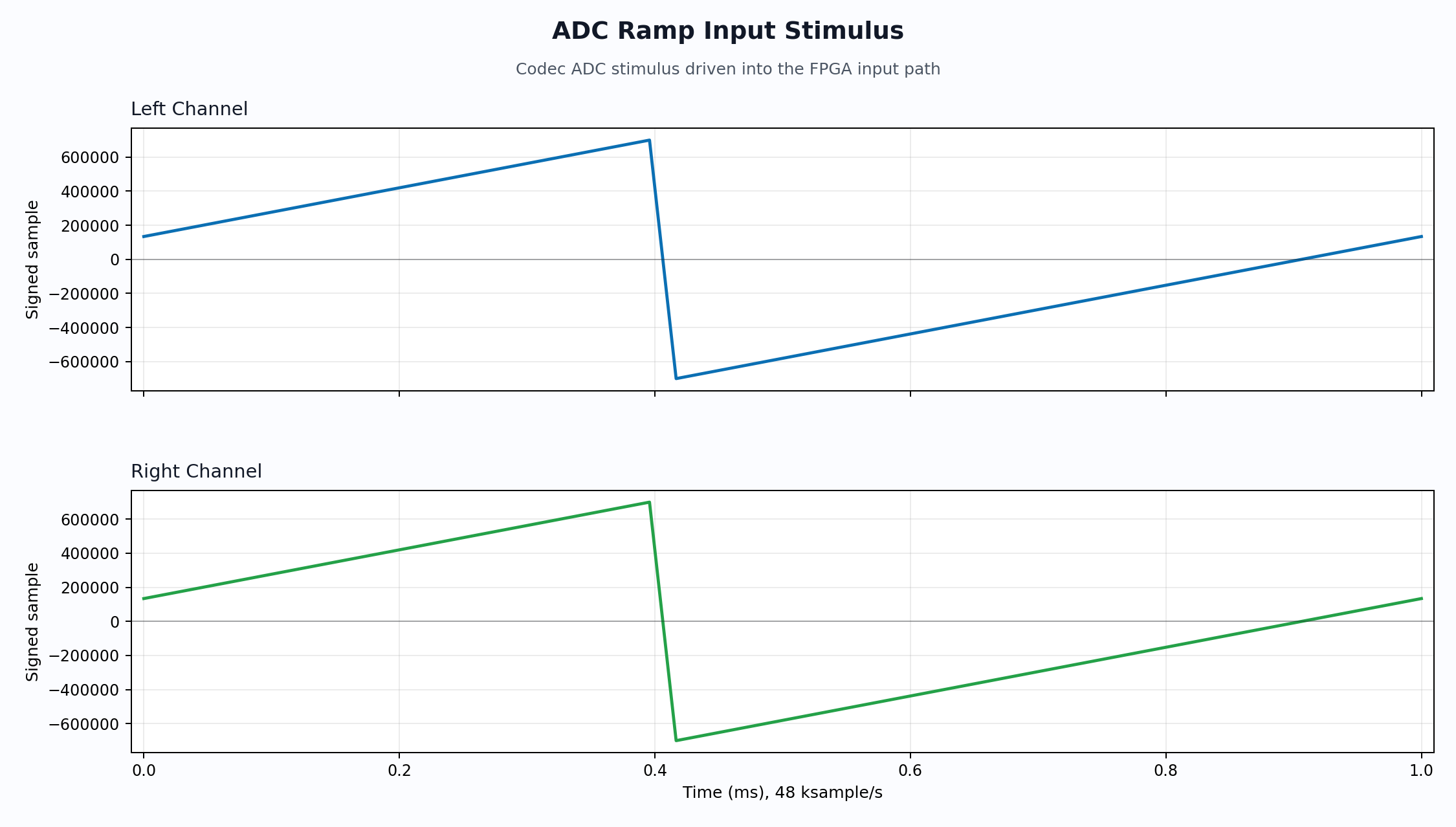
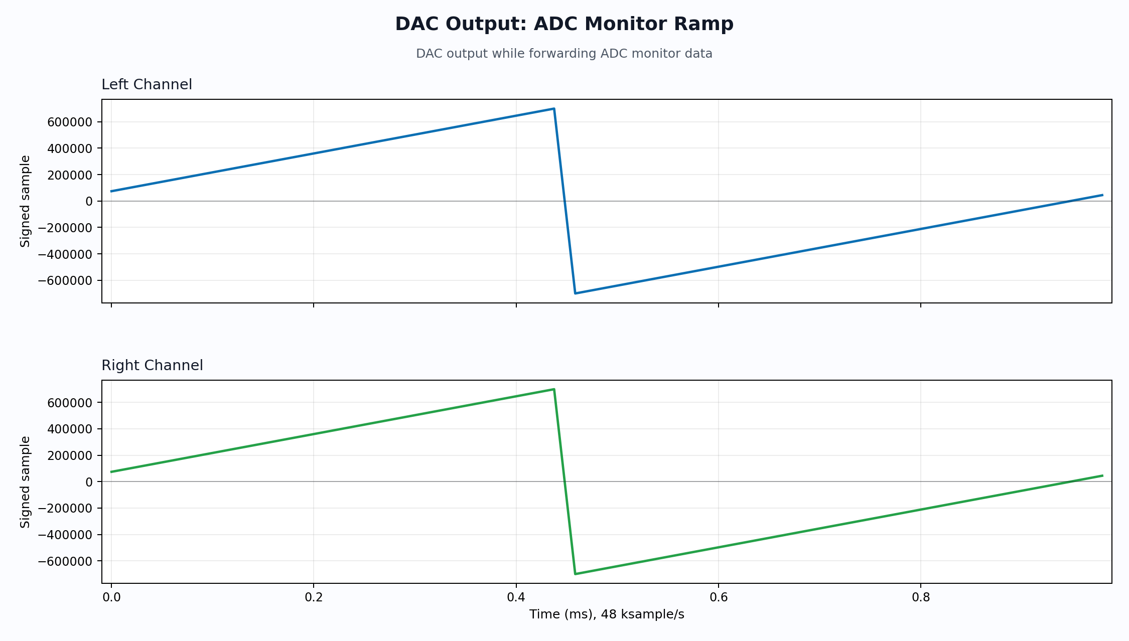
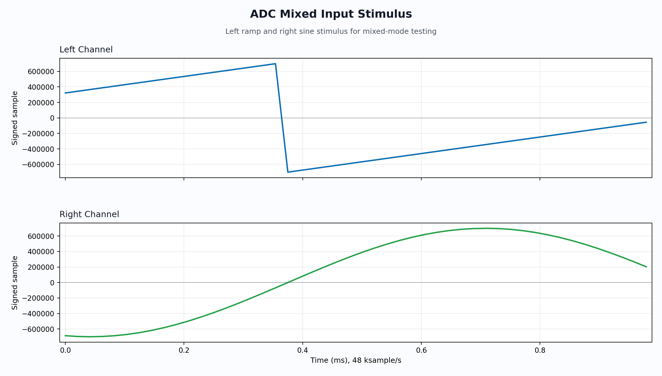
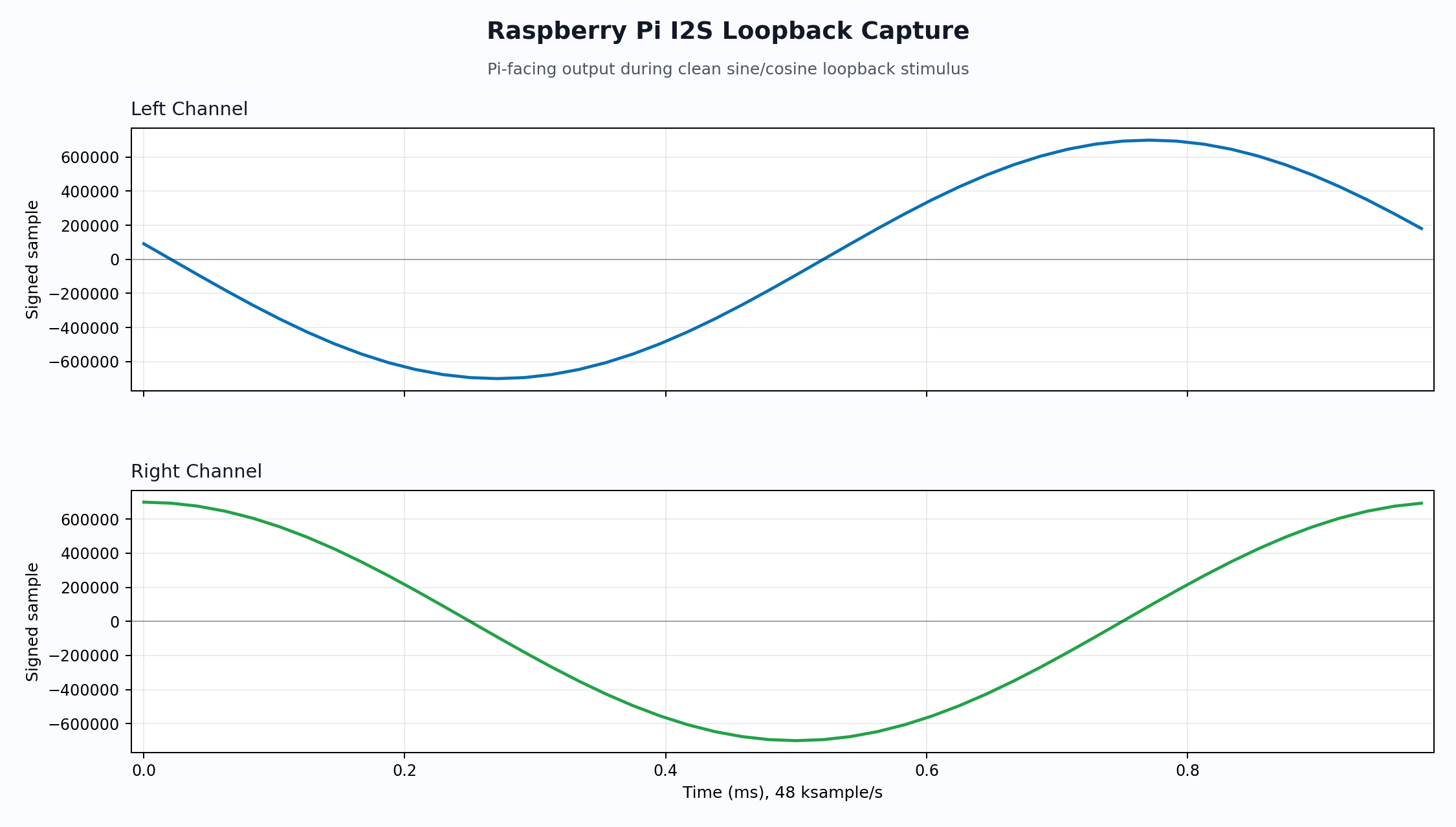
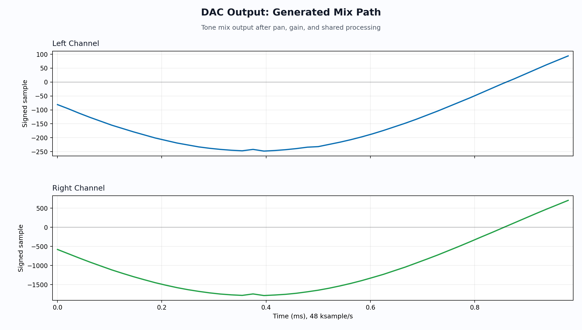
The plots below come from the top-level GHDL simulation of the integrated design. Each figure separates left and right channels into independent XY plots so channel behavior is easier to inspect.
Shared Math And Resource Strategy
The key optimization is shared math. Audio designs can become expensive quickly if every oscillator, voice, filter, and output stage owns a full set of multipliers. That approach may be simple to reason about, but it wastes fabric and makes scaling difficult.
The FPiGA Audio Hat design instead uses a deterministic shared datapath where appropriate. The shared output stage folds pan, gain, and EQ-oriented processing into a TDM schedule. This lets the design use hard multiplier resources efficiently while still preserving a bounded processing window per sample.
The polyphonic synth path also benefits from explicit memory organization. Voice configuration is stored in Gowin DPB-backed structures rather than large ad hoc register arrays. The scheduler reads frequency, control, volume, and ADSR fields for each voice and pipelines work across table reads, interpolation products, volume products, and accumulation. This makes the implementation more resource-conscious and easier to extend.
The current documented Gowin `GW5A-LV25MG121NC1/I0` utilization is:
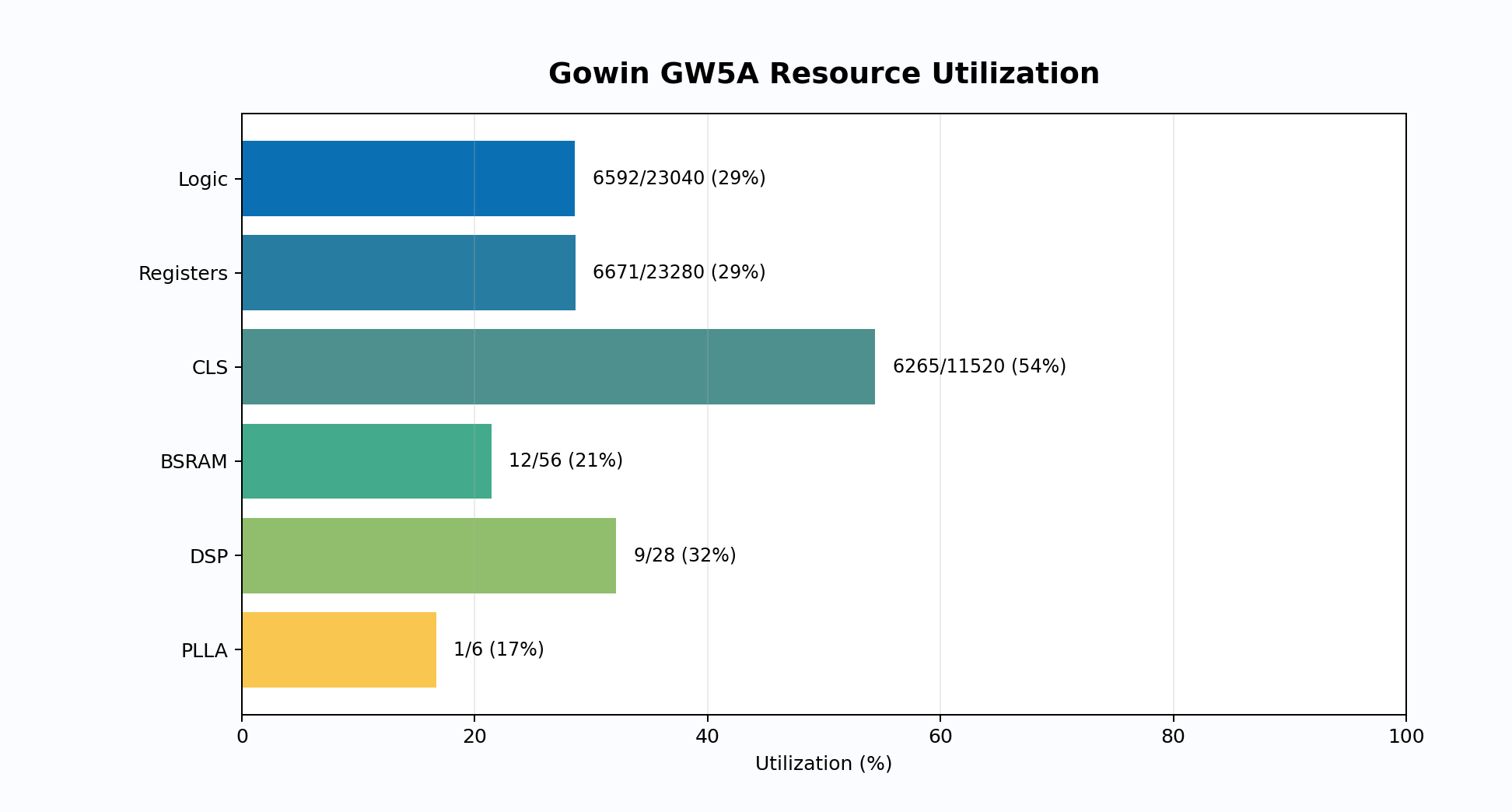
Those numbers leave useful room for board support logic, additional voices, additional synthesis modes, richer control surfaces, or deeper debug capture. The important part is that the design is not barely fitting. It has an architecture that can keep evolving.
Simulation Strategy
The top-level simulation drives the actual `radhdl_fpiga_audio_top` entity rather than testing a narrow internal block. The testbench:
Generates the 50 MHz input clock.
Waits for modeled clock/reset stabilization.
Drives I2C register writes.
Exercises mute control.
Drives codec ADC I2S stimulus.
Captures codec DAC I2S output.
Drives Raspberry Pi-facing I2S stimulus.
Captures Raspberry Pi-facing loopback output.
Enables synthesizer modes through registers.
Writes interleaved signed 32-bit little-endian sample files.
Generates quick-look PNG plots.
That gives the project a stronger regression point than a collection of isolated unit tests. The board-level routing, register map, I2S timing, DSP selection, and output serialization all have to cooperate before the plots look reasonable.
The simulation can be launched from the RadHDL repository root:
For quick article plots, the run can be shortened:
RADHDL_AUDIO_CAPTURE_FRAMES=48 \

RADHDL_AUDIO_PLOT_SECONDS=0.001 \

RADHDL_AUDIO_WAVE_HZ=1000 \

projects/examples/fpiga_audio_hat_shared_math/sim/run_audio_hat_shared_math_top_ghdl.sh
The sample captures are written as signed 32-bit little-endian stereo data at 48 ksample/s. That format is intentionally simple so it can be inspected with Python, NumPy, MATLAB, Octave, or a notebook without needing a special viewer.
Signal Path Checks
The ADC ramp stimulus confirms that the codec-facing input generator is producing the intended signed sample data into the FPGA path.
The DAC ADC monitor capture verifies that the ADC monitor path reaches the codec DAC output. In this mode, the output is expected to track the incoming ADC stimulus after the design's capture and framing latency.
The mixed ADC stimulus provides a separate input case where left and right channels are intentionally different. That is useful for catching lane swaps, sign-extension errors, and accidental mono behavior.
The Raspberry Pi loopback capture validates the Pi-facing I2S side using a clean stimulus. This is especially important because Pi-facing and codec-facing buses have different ownership expectations in real hardware. The FPGA generates the clocks for the Pi-side test path in this setup, then the testbench verifies captured output against the expected active audio behavior.
The generated mix path exercises the synthesizer and shared output processing together. This is a more complete stress point than a raw oscillator plot because it goes through mode selection, tone generation, pan/gain choices, and the shared output datapath.
Debug Path
The design includes RadDebugHub and RadILA so internal visibility does not depend solely on vendor-specific debug IP. That is a major product-level advantage. Vendor ILAs are useful, but they tend to lock a design into a particular toolchain, project database, and JTAG workflow. A portable debug hub gives us another option: capture internal state through the same kind of register-facing infrastructure used by normal software control.
For this project, the debug hub can expose live status, event metadata, capture status, and sample readback. The debug I2C smoke path is optional in the simulation runner because full board bring-up should still validate the live electrical path, but the register-level infrastructure is already integrated.
RADHDL_AUDIO_DEBUG_I2C_SMOKE=1 \

projects/examples/fpiga_audio_hat_shared_math/sim/run_audio_hat_shared_math_top_ghdl.sh
Build Flow
The Gowin build is launched from the RadHDL repository:
projects/examples/fpiga_audio_hat_shared_math/build_gowin.sh
The project-local Gowin TCL, constraints, RadHDL source list, and example project metadata define the FPGA target, top-level entity, pinout, and source structure. This is also the kind of project RadBuild is meant to formalize further: the source tree remains readable and versionable, while generated vendor artifacts stay outside the clean source-of-truth path.
This is where RadHDL and RadBuild fit together. RadHDL provides the reusable HDL blocks and documentation. RadBuild provides the declarative project layer that can drive vendor tools, package source assets, generate documentation, and eventually produce repeatable board images or system bundles.
Why This Is A Good Demonstration
The FPiGA Audio Hat is a strong demonstration because it is not just an LED blink or a synthetic benchmark. It touches real product concerns:
Board-level clocking.
External codec timing.
Host-facing I2S.
I2C software control.
Register maps.
Audio synthesis.
Shared DSP resource scheduling.
Debug capture.
Vendor primitive usage.
Simulation artifacts that can be plotted and reviewed.
That combination is exactly where FPGA projects often become hard to maintain. A small demo can be clean, but a full board design can quickly become tied to one tool version, one vendor IP flow, one board, and one engineer's local scripts. RadHDL is intended to fight that by making reusable blocks, explicit primitives, generated datasheets, and repeatable build paths normal.
What Comes Next
The next article should cover hardware bring-up: programming the Gowin device, verifying MCLK/BCLK/LRCK on pins, confirming I2C register access, reading RadDebugHub status live, checking codec behavior, and listening to generated audio through the Hat. The simulation work does not replace hardware validation, but it gives bring-up a much better starting point.
The follow-up work should also expand the user-facing control side. A small host tool or RADLib UI can expose oscillator selection, voice gates, wavetable selection, gain, pan, LFO depth, and debug capture as live controls. That turns the project from a verified HDL design into an instrument.
The broader message is simple: FPGAs are excellent for audio DSP when the design is structured correctly. The fabric can keep timing deterministic, keep latency bounded, and expose exactly the hardware parallelism the signal path needs. With RadHDL, that capability becomes easier to reuse, document, test, and move between projects.
Relevant Links